
Selection Guides
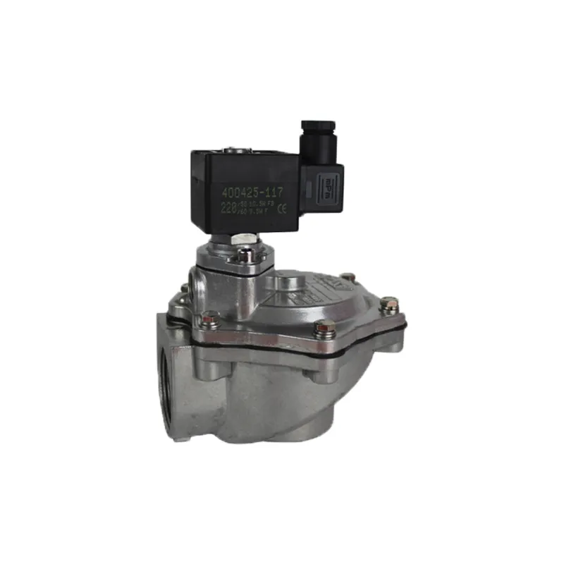
Specifying a dust collector pulse valve: the ASCO Series 353
Sizing and specifying ASCO Series 353 pulse valves for pulse-jet baghouses: orifice and Kv by size, diaphragm choice, pilot options and spare kits.
- Written by
- A.N Trader technical team
- Published
- Reading time
- 7 min read
A pulse valve in a baghouse does something no other valve on the plant does: it opens completely, dumps the contents of an air header down a blow tube, and shuts again, thousands of times a day, for years. Nothing about that duty is served by a general-purpose solenoid valve. It needs a large orifice relative to its port, a diaphragm built for cycle life rather than sealing pressure, and an operator that will survive being mounted outdoors on a dusty plenum.
This article covers how to specify one from the ASCO Series 353 leaflet — the dual-stage, integral-pilot diaphragm valves in threaded and compression-fitting bodies, which is what most Pakistani cement, textile and food plants have fitted.
What the pulse actually does
Pulse-jet cleaning does not blow dust off the bag. It fires a short, high-energy jet down the blow tube and into the bag’s venturi, entraining a much larger volume of plenum air behind it. That slug of air travels down the bag, snaps it outward, and the dust cake releases into the hopper. Cleaning energy comes from the rate of pressure rise inside the bag, which is why opening speed and flow coefficient matter more than the valve’s pressure rating.
Two consequences follow. An undersized valve does not clean weakly — it can fail to clean at all, because the pressure wave never develops. And oversizing costs compressed air on every pulse for the life of the plant, which is real money on a 200-valve baghouse.
The range, by the numbers
| Connection | Pipe size | Orifice | Kv | Flow | Min. differential | Max. differential (PS) | Catalogue number | Weight |
|---|---|---|---|---|---|---|---|---|
Threaded G | 1 1/2 | 50 mm | 44 m³/h | 733 l/min | 0.35 bar | 8.5 bar | G353A047 | 1.40 kg |
Threaded G | 2 | 66 mm | 77 m³/h | 1290 l/min | 0.35 bar | 8.5 bar | G353A050 | 2.90 kg |
Threaded G | 2 1/2 | 66 mm | 92 m³/h | 1540 l/min | 0.35 bar | 8.5 bar | G353A051 | 2.60 kg |
| Threaded, external male | 3 | 76 mm | 170 m³/h | 2833 l/min | 1 bar | 6 bar | G353D060 | 4.10 kg |
Compression fitting Ø | 1 1/2 | 50 mm | 44 m³/h | 733 l/min | 0.35 bar | 8.5 bar | G353A065 | 1.75 kg |
Weights include coil and connector with the standard SC operator. The catalogue number above is the valve body; the ordered part carries the operator prefix in front of it, which is why the 1½ in threaded valve is quoted as SCG353A047.
The row that most often surprises people is the 3 in. It is not simply “the big one” — its pressure window is different. Where every other size works from 0.35 bar up to 8.5 bar, the G353D060 needs a minimum of 1 bar and is limited to 6 bar. It also has an external male thread rather than a female one, and at 4.10 kg it is nearly three times the weight of the 1½ in. Check the header’s working pressure against that 6 bar ceiling before ordering.
Note also that the 2 in and 2½ in bodies share the same 66 mm orifice; you are buying connection size, not a larger flow path.
Diaphragm selection
The diaphragm is the wear part and the temperature limit, and there are two:
| Diaphragm | Fluid temperature range | Use it when |
|---|---|---|
CR (chloroprene) | -20 to +85 °C | Standard. Ambient-temperature compressed air. |
FPM (fluoroelastomer) | -20 to +120 °C | Hot header air, or where the leaflet’s optional FPM suffix is called for by the process |
The ambient temperature range for the valve is -20 to +85 °C regardless. The leaflet describes the diaphragms as reinforced and wear-resistant, and confirms FPM is available on all five catalogue numbers using the optional suffix letter — you do not change valve body to get it.
Two construction details on the same subject matter more than they look. The leaflet footnotes tell you which bodies contain a spring above the main diaphragm as standard — the G353A047, G353D060 and G353A065 — and which have it available on request, the G353A050 and G353A051. That matters because the installation note says the valves can be mounted in any position without affecting operation only for those spring-fitted constructions. If you are mounting the valve anything other than the way the original was mounted, this is the footnote to check.
Materials in contact with the air are aluminium body, stainless steel core tube, core, plugnut and core spring, NBR sealings and disc, and a copper shading coil.
Pilot and operator options
The Series 353 is an integral-pilot design: the solenoid operator sits on the valve and pilots the main diaphragm directly. The operator is an epoxy-moulded class F coil, IP65, with an operator temperature range of -20 to +85 °C and a spade-plug connector to ISO 4400 for cable of Ø 6 - 10 mm. Electrical safety is to IEC 335.
Standard coil voltages are 24 V DC and 24 V, 115 V or 230 V AC at 50 Hz, with other voltages and 60 Hz on request. Power ratings as tabulated:
| Coil | Inrush | Holding | Replacement coil |
|---|---|---|---|
CMXX-FT (AC) | 55 VA | 23 VA / 10.5 W | 400425-117 (230 V/50 Hz) |
CMXX-FF (DC) | — | 14 / 19.7 W hot/cold | 400425-342 (24 V DC) |
The same valve body accepts a range of operator prefixes — SC, WP, SG, ATEX EM (T) and NF — and the leaflet marks every one of them as available on all five catalogue numbers. That is the practical point: you do not change valve when the area classification changes, you change operator. The published options are a waterproof enclosure with embedded screw-terminal coil to IP67, CEE 10; explosionproof solenoids for hazardous locations to ATEX and national standards; IECEx certification; a plug with visual indication and/or peak-voltage suppression; an electronic timer; and, on the 3 in only, hose-connection executions.
One dimensional consequence to plan for: choosing the ATEX II3D SG operator instead of the standard SC grows the operator envelope. On the G353A047, dimension A goes from 80 to 89 mm and G from 45 to 50 mm, while overall length L drops from 178 to 174 mm. On a tightly spaced valve row, check the leaflet’s dimension table before assuming a like-for-like swap.
Threaded, compression fitting, and what this leaflet does not cover
The G353A047 and G353A065 are the same valve internally — same 50 mm orifice, same Kv 44, same spare-parts kit — differing only in how they land on the header.
- Threaded (
G, toISO 228/1) is the conventional connection. Other pipe threads are available on request. - Compression fitting achieves tightness through a compressed gasket on the blow tube, and the leaflet notes that using rubber gaskets as the sealing member tolerates slight misalignment in the piping. On a retrofit into an existing, slightly out-of-true blow-tube row, that tolerance is the reason to pay the extra
0.35 kgand choose theG353A065.
This leaflet covers remote-mounted valves — bodies that thread or clamp onto a header outside the collector. Immersion or tank-mounted constructions, where the valve body sits inside the air receiver, are a different construction with their own leaflet and their own dimensions. If your baghouse uses immersion valves, do not cross-reference from the figures above; ask for the immersion series data specifically.
Spare parts kits
| Catalogue number | Kit (AC) | Kit (DC) |
|---|---|---|
SC G353A047, SG G353A065 | C113827 | C113827 |
SC G353A050, SC G353A051 | C113685 | C113686 |
SC G353D060 | C123432 | C123433 |
The grouping follows the internals rather than the label: the two 50 mm orifice valves share a kit, as do the two 66 mm valves. Confirm the kit number against the leaflet for your exact catalogue number and coil supply before ordering a batch.
Sizing for cement and for textile
The two industries pull in opposite directions and the same catalogue serves both.
Cement — kiln, clinker cooler, packing plant and crusher collectors run large bag counts, coarse abrasive dust and high ambient temperatures. Rows are long, so valves tend to be 2 in and above. The specification questions are diaphragm temperature rating, the operator’s ingress class where dust is continuous, and cycle life. Continuous dust makes the waterproof IP67 operator worth the money even with no washdown.
Textile — extraction in blowroom, carding and spinning is lighter dust, finer bags, shorter rows, usually indoors. 1½ in valves are common, and the compression-fitting body earns its place because retrofit rows are rarely perfectly aligned. In a humid area, specify the waterproof operator rather than the standard one.
In both cases the sizing itself belongs with the collector manufacturer: valve size is set by the blow tube and venturi it has to drive, the bags per row, and the header pressure available. What the table above lets you do is check the valve you have been asked to supply is inside its published pressure window, confirm the orifice matches what the collector was designed around, and catch the two traps — the 3 in valve’s narrower pressure range, and the mounting-position restriction on bodies without the diaphragm spring.
Products mentioned
Related guides
-
Selection Guides
How to select a valve positioner: linear vs rotary, smart vs electro-pneumatic
A decision guide to specifying a valve positioner: actuator motion, single or double acting, feedback options, area classification and when smart pays.
-
Troubleshooting
Air preparation for valve positioners: why the filter regulator matters
Instrument-air quality decides whether a positioner holds position. What the YTC manuals require, the fault codes bad air produces, and YT-200 sizing.
-
Comparisons
I/P converters explained: selecting between the YT-930 and YT-940
What an I/P converter does, how the Rotork YTC YT-930 and YT-940 differ on protection concept and supply banding, and why converters fail in service.